Click here to sign up. The flexural design strength of compact beams laterally supported is given by.
17 Cb Bending Coefficient Part 1 For Steel Beams
The basic provisions related to design and evaluation of bending members in the structural steel specifications either according to Load and Resistance Factor Design LRFD1 or Allowable Stress Design ASD2.

. The 14th edition combines both methods in one volume and provides common requirements for analyses and design and. The steel beam design worked example elaborates the design of a simply supported beam having a uniformly distributed load. Enter the email address you signed up with and well email you a reset link.
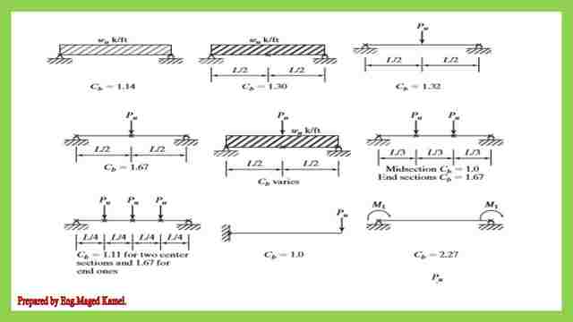
Its value is highest Cb1 when the moment diagram is uniform between adjacent bracing points. On the Model Settings - Codes tab select the steel code from the drop down list. Yaw c Draft date October 21 2012 1 Moment Limit State In steel design it is often necessary to design a beam to resist bending moments.
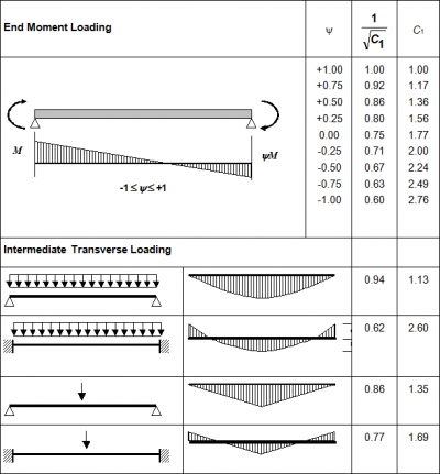
Log in with Facebook Log in with Google. The equations for evaluating the moment-gradient factor Cb given by AISC in Load and Resistance Factor Design Specification for Structural Steel Buildings are empirical equations. The load and resistance factor design approach is recommended by AISC for designing steel structures.
Free AISC Steel and NDS Wood Beam Design Our goal with WebStructural is to give back to the engineering community by providing a free cloud-based steel and wood. 8 and φb 090 Example 1 A W 16 x 36 beam of A992 steel Fy 50 ksi supports a concrete floor slab that provides continuous lateral support to. The Significance and Application of Cb in Beam Design Engineering Journal American Institute of Steel Construction Vol.
Steel Design Structural design standards for steel are established by the Manual of Steel Construction published by the American Institute of Steel Construction and uses Allowable Stress Design and Load and Factor Resistance Design. The beam is considered as simply supported and the design data for calculating the bending moment and shear forces are given below. How To Apply a Steel Design Code.
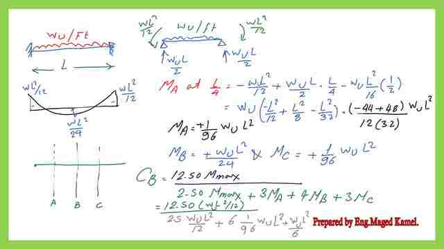
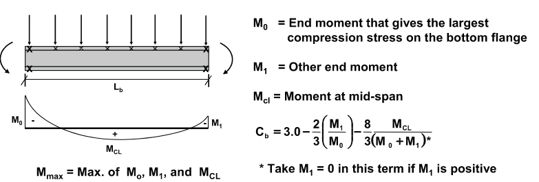
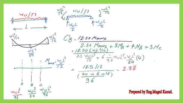
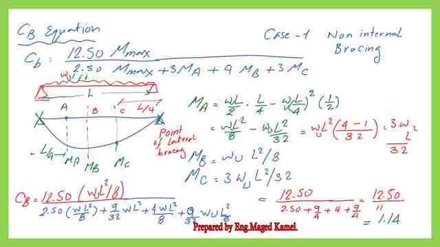
Cb in AISC beam design has been calculated using Mmax and three 14 point moments along the unbraced length M A M B and M C. Bending Coefficient Cb Cb is a moment coefficient to account for the effect of different moment gradients on lateral - torsional buckling Cb 10 for a uniform moment diagram Which represent the worst case of compression flange buckling resulting in the least beam moment resistance In general Cb 125 M max 25 M max 3 M A 4 MB 3 MC M M MA. The beam design is not governed by lateral-torsional buckling.
On the Hot Rolled tab of the Beams Spreadsheet or the Steel tab of the Columns Spreadsheet enter the appropriate bracing information and factors. A review of the literature on. It can be understood as follows.
Segui Steel Design 6th. It is conservatively prescribed as 1. Select the lightest section from the AISC Manual design tables.
Cb 125M max ----- 25M max 3M A 4M B 3M C. 13 Lateral Torsional Buckling cont Moment Gradient Factor Cb The moment gradient factor Cbaccounts for the variation of moment along the beam length between bracing points. The beam design is governed by lateral-torsional buckling but the capacity is limited to the plastic capacity Mp.
From page of the AISC manual select W16 x 26 made from 50 ksi steel with φbMp 1660 kip-ft. Besides printing Cb as 1 in the design report RE adds a note at the bottom of the report saying Cb not calculated for the Lb specified. Steel Design - LRFD AISC Steel Manual 14th edition Beam Limit States Professor Louie L.
However if theres a value in the Cb cell other than zero 0 then that value is. Close Log In. This is a link to download the pdf file used for the illustration of this post.
The BRB strain at two times design story drift was estimated using 2ø BRB CdFyMinEρIe this equation conservatively assumes the yield strength of steel core is fully utilized and shall yield an upper bound of beta omega factors. WU 12 wD 16 wL 142 kips ft. 2 - Click the database access button and select from the built-in AISC section database.
Remember me on this computer. φbMn φb Fy Zx φb 15 Fy Sx Eq. Given by ASCE 7-98 are nominal loads not maximum or ultimate - During its design life a structure can be subjected to some maximum or ultimate.
CB value 125012 4296cb961250 42128125042238. Design with ASD and LRFD are based on the same nominal strength for each element so that the only differences between the approaches are the set of load combinations from ASCESEI 7-16 used for design and whether the resistance factor for LRFD or the safety factor for ASD is used. In order to design the beam according to LRFD M n must be determined for the trial beam selected.
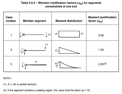
1 - Simply type the AISC name into the Steel Section Name field and press Tab. Cantilever Flexural Member Design By Sam Eskildsen PE Structural Design Group Birmingham AL Answer Introduction The AISC 1999 Load and Resistance Factor Design Specification for Steel Buildings1 has no specific flexural design requirements for cantilever beams beyond requiring Cb 1 when the free end is unbraced. 3 - Click the Design button to have the module evaluate steel sections from the database according to your criteria.
Determine the ultimate loads acting on the structure - The values of D L W etc. MU wu L 2 8 142 x 302 8 15975 kip-ft. For the next post Cb The coefficient of bending part-2.
Kf was calculated based on the geometries of BRB connection and beamcolumn etc. Fo r more detailed illustrations for the CB please follow this Flexural Limit State Behavior. By the AISC Committee on Manuals Mark V.
When this occurs the modification factor does not affect the capacity or only marginally affects the capacity by pushing it to the plastic capacity limit. If you need full design checks via AISC 360 NDS ASD and LRFD for steel or wood beam design and you want to design your next beam in minutes you might like our Beam Designer tool. Calculate the factored design loads without self-weight.
Cb Value For Crane Rail Beam Simply Supported By Hangers Attached To Top Flange Only Structural Engineering General Discussion Eng Tips
Beam Lateral Torsional Buckling Cb Yura Equation Limits Existing Steel Beams Structural Engineering General Discussion Eng Tips
17 Cb Bending Coefficient Part 1 For Steel Beams
Cb And Lb For Cantilever Column Structural Engineering General Discussion Eng Tips
Cb Moment Distribution Steel And Concrete Design Youtube
17 Cb Bending Coefficient Part 1 For Steel Beams
17 Cb Bending Coefficient Part 1 For Steel Beams
Member Design Steelconstruction Info
0 comments
Post a Comment